I like that phrase "constellation of holes"...
You also need to provide for tension of the belt. That is typically done in these mountings by having the motor bolts fit in slots so it can slide to tension the belt. Some of the mounts have a tensioning screw that pulls the motor sideways in the slotted holes, I did it with a quick clamp. These sorts of setups would make the step face (bosses) unusable for positioning the motor except perhaps in one direction parallel to the belt axis (the line between motor and shaft centers).
On mine I ended up making a plate that fit over the face of the motor to give more surface area to the contact between it and the mounting plate. That plate is 1/8" thick to match the height of the stepped face boss on the motor. Photos and details here:
http://dan.pfeiffer.net/10m/electric_drive_unit.htm
There may be better solutions to this. I had planned to cut recesses in the back of the mounting plate to receive the bosses on the motor but it was all a bit too tricky for me to machine with the needed precision on the manual mill I have. I'm sure a CNC setup could do it without difficulty. The spacer plate was simpler for me but this setup does rely on the friction from the motor mounting bolts holding to motor to the plate. And you want to be sure to have as much engagement as possible of those bolts in the aluminum holes on the motor.
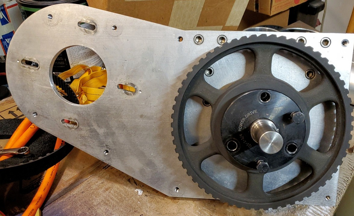
You also need to consider the thickness of the mounting plate and how far out the shaft of the motor extends from the surface to accommodate the proper mounting of the drive pulley. It needs to engage with the shaft and while there is some leeway there if the mounting plate is too thick you won't have enough of the shaft sticking out past the plate to get the pulley on. If you look at the photos of my mounting plate you can see that the hole where the motor shaft comes through is large enough for the pulley to fit through.
http://dan.pfeiffer.net/10m/edrive_IMG_20211121_014845.jpg
I need to mount the pulley to the motor shaft before the motor was mounted to the plate because the mounting bolts are on the back side of the pulley bushing. If there were through holes on the pulley bushing it could be done from the front but this size bushing doesn't have that. I thought about drilling them and if I needed a larger drive pulley I might have had to.
Another reason I used the 3/4 thick aluminum plate for my mount was that I could recess the fastener heads in the plate and get the belt closer to the surface of the plate for a tighter fit. I also cut a recess in the back of the plate for the motor to sit in so the shaft would stick out far enough from the face for proper mounting of the drive pulley.
Dan Pfeiffer
Note also: Many (most?) motors have a face with a step. This is useful in that your plate can have a hogged out section that mates with that step such that the motor's XY location gets fixed by that interface and not your bolt pattern. At that point, the bolt holes can be fairly loose since they are for the most part merely pulling the motor tight against the plate and the plate friction and that step interface keep the motor secure. Of course the bolts also keep the motor from rotating on the plate by their being hole-aligned with the motor holes and bolts going thru them.
From: electricboats@groups.io [mailto:electricboats@groups.io] On Behalf Of Myles Twete
Sent: Monday, February 7, 2022 10:00 AM
To: electricboats@groups.io
Subject: Re: [electricboats] Bolt hole tolerance when laser cutting 1/2 inch stainless steel
Caveat: I am an engineer, but not mechanical.
Having said that, I've done some mechanical engineering designs and chosen hole sizes on parts during a couple of my contracts.
Realize that these are interfaces.
And sure, with single holes, you might get away with a close or tight tolerance for that each hole.
But even then, the fastener choice matters and perhaps a heavily plated, poorly toleranced or non-standard bolt gets spec'd and won't fit the hole that standard bolts would.
And there's a big difference between single, non-dependent holes vs a constellation of holes as you are defining for mounting the motor to the plate. And for that part of your design, you should consult the motor manufacturer's mechanical drawing for the motor. And if that does not inform as to spacing tolerances for the motor holes, then ask them. For sure, when you are dealing with a constellation of dependent holes, your hole diameters will need to be at least a little bit larger to accommodate the worst case sum of the tolerances of (1) motor hole spacing, (2) your plates matching hole spacing, (3) other factors?
In case this helps....
From: electricboats@groups.io [mailto:electricboats@groups.io] On Behalf Of Steven Borg
Sent: Sunday, February 6, 2022 5:37 PM
To: electricboats@groups.io
Subject: [electricboats] Bolt hole tolerance when laser cutting 1/2 inch stainless steel
Progress continues on the 55' electric motor conversion.
Next question: When laser cutting my 1/2" stainless steel plate for the motor mount (or other parts), what hole tolerance should I consider?
I get different answers when I look online: Clearance Hole Chart (amesweb.info)
suggests that for a 1/2" bolt a 'close' fit I should be between .531 and .538, and 'loose' fit .609 and .625 with 'normal' fit in between.
But other sites are more prescriptive, telling me that I should use .5156 for a tight fit and .5312 for a loose fit. (basically 1/64" clearance for tight, and 1/32" clearance for loose. Clearance Hole Size for Bolts and Screws (Imperial) - The Engineer's Bible (engineersbible.com)
And, I've heard people say just always add 1/16" to nearly every size bolt hole.
Given SendCutSend and everyone else seems to have a tolerance of +/- .005", I'm struggling to understand what kind of fit I should go for. I'd hate to have a motor plate whose 4 support holes were just far enough off to not be able to mount the motor... :-O
Hoping there are a few folks who've been through this before!
:-)
Steve
No comments:
Post a Comment